

频率范围可达DC-400MHz,内置6GHz Channel 3
每秒12位的精确测量40ps时间间隔分辨率
绝佳的万用特色
完整的数学运算功能及简易的操作面板
快速测量及特殊应用
免费的远端操控软件及常用的SCPI指令
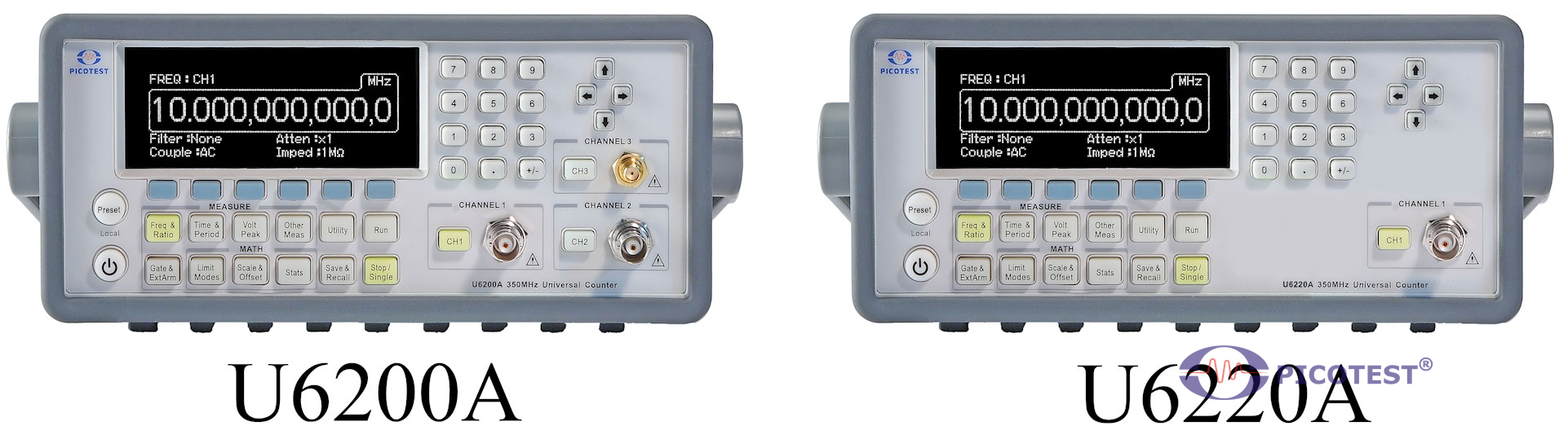
注意 : 红色字体为U6220A 没有提供的功能
12位分辨率 含6GHz频率测量
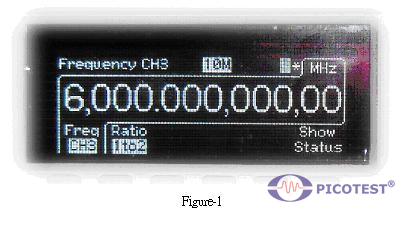
本公司根据ISO9004制程所生产出的U6200A通用频率计数器能够提供每秒12位数频率分辨率(见Figure-1)、40 ps时间间隔解析,以及完整的测试与分析功能。另外,本产品还内建第三频道,可量测频率从375 MHz到6GHz,而第一和第二频道,可量测频率从1 mHz到 to 400 MHz。
绝佳的万用特色
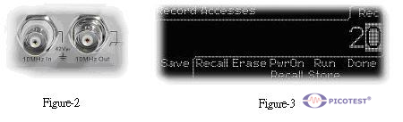
本产品U6200A也提供了其它不错的功能及设计,例如:频率比率(每秒11位)、时间间隔、周期(2.5 ns至1000 s)、 工作周期、脉冲宽度、上升/下降时间、峰值电压( 100 Hz到300 MHz)、相位、总计、时基温度变化稳定度(小于1 PPM)、老化率(每年小于2 PPM)、时基参考(I/O见Figure-2)、前端完全隔离。另外还提供20组设定存储空间,让使用者储存常用的设定(见Figure-3)。
完整的数学运算功能及简易的操作面板
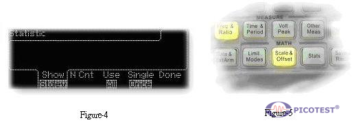
本产品U6200A内建统计及数学运算功能。使用者可以做一般量测、同步量测、中间值统计、最大/最小值统计、三角函数统计及标准差统计(见Figure-4)。以及运用Scale & Offset功能按键,使用者可依实际应用加入补偿值。而要完成以上操作并根据需求输入数值,使用者只需轻易地利用本产品面板上的数字键即可。再者,本公司为了使用者操作方便,将功能按键设计成当功能启用时,按键便会亮起(见Figure-5)。
快速测量及特殊应用
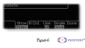
本产品U6200A采用即时数字信号进程技术,即可在分析数据之际,同时读取新值并做快速测量。值得一提的是「限值模式」,使用者可以依需求设定最大及最小值,并通过面板设定成Go-On或Stop,再开启USB Output,此时只要测量值超过所设定的范围, U6200A就会按照设定继续或停止测量,同时输出信号触发外部装置(见Figure-6)。
免费的远端操控软件及常用的SCPI指令
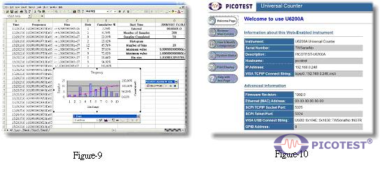
使用者除了可以通过微软Excel应用软件(见图九),经由内建的USB或选购的GPIB接口取得资料,还可以利用U6200A支持网路伺服器功能,将内建的网络通信接口连结PC ,并在PC上的浏览器中输入预设的位址192.168.0.247,使用者便可通过网络操作界面GUI(见Figure 10)操控U6200A。另外,靠着与安捷伦53132A相容的SCPI指令集,U6200A能够在应用上提供使用者熟悉的语法字串。相关指令集信息,请参照使用U6200A使用手册第七章节。
U6200A / U6220A 规格表
A.规格表
本附录包含 U6200A/220A 的规格。 它涵盖了各种条件下的交流、直流、电阻、温度和频率/周期特性。 为方便起见,它还包含一般特性和精度计算。 我们付出了很多努力来确保这些规范满足您的生产、工程和/或研究需求。 除非另有说明,否则所有规格均适用于 U6200A/220A。
※ 注意:U6220A 不提供绿色规格。
|
Channel 1 & 2 (for U6200A only) Input Specifications |
||
|
DC Coupled |
1mHz to 400 MHz |
|
|
AC Coupled |
200KHz to 400 MHz (50 Ω) 30 Hz to 400 MHz (1 MΩ) |
|
|
FM Tolerance |
FM Tolerance: 25% |
|
|
Voltage Range and Sensitivity |
||
|
1mH to 225 MHz |
20 mVrms to ±5 V ac + dc (Medium and High) 25 mVrms to ±5 V ac + dc (Low) |
|
|
225 MHz to 400 MHz |
30 mVrms to ±5 V ac + dc |
|
|
Channel 1 & 2 (for U6200A only) Input Characteristics |
||
|
Impedance (ATT X 1, 1 MΩ Capacitance) (ATT X 10, 1 MΩ Capacitance) |
1 MΩ or 50 Ω 24 pF 15 pF |
|
|
Coupling |
AC or DC |
|
|
Low-Pass Filter |
100 KHz (or disabled) –20 dB at > 1 MHz |
|
|
Input Sensitivity |
Selectable between Low, Medium(default), or High Medium is approximately 1.35x High Sensitivity, low is approximately 1.7x High Sensitivity |
|
|
Internal Noise |
200uVrms(typical) |
|
|
|
||
|
Voltage Range and Sensitivity (Single-Shot Pulse) |
||
|
1.5ns to 10ns Pulse Width |
80 mVpp to 10 Vpp (150 mVpp with optional rear connectors) |
|
|
>10 ns Pulse Width |
50 mVpp to 10 Vpp (150 mVpp with optional rear connectors) |
|
|
|
||
|
Trigger Level(ATT x 1) |
||
|
Range |
±5.125 V |
|
|
Accuracy |
±(15 mV + 1% of trigger level) |
|
|
Resolution |
2.5mV |
|
|
ATT x 10 Range |
X 10 |
|
|
Trigger Slope |
Positive or Negative |
|
|
Auto Trigger Level |
Range |
0 to 100% in 1% steps |
|
Frequency |
Peak Voltage fast mode >10 KHz Peak Voltage slow mode > 100 Hz Amplitude> 100 mVpp (No amplitude modulation) |
|
|
|
||
|
Damage Level |
||
|
DC~400MHz 50 Ω |
12 Vrms |
|
|
0 to 3.5 kHz, 1 MΩ |
350 V dc + ac pk |
|
|
3.5 kHz to 100KHz, 1 MΩ |
350 V dc + ac pk linearly derated to 12 Vrms |
|
|
100KHz to 400MHz, 1 MΩ |
12 Vrms |
|
|
Attenuator |
||
|
Voltage Range |
x10 |
|
|
Trigger Range |
x10 |
|
1. 通道 1 和 2 的规格和特性对于通用和独立配置是相同的。
2. 显示的值适用于 x 1 衰减器设置。 使用 x 10 衰减器设置时,将所有值乘以 10(标称值)。 请注意,可能需要在应用环境中(尤其是在高温下)重新校准输入偏移,以实现最大灵敏度。
|
|
||||||||||
|
Channel 3 Input Specifications (for U6200A only) |
||||||||||
|
Frequency Range |
375 MHz to 6 GHz |
|||||||||
|
Channel 3 Input Characteristics (for U6200A only) |
||||||||||
|
Impedance |
50 Ω |
|||||||||
|
Coupling |
AC |
|||||||||
|
VSWR |
< 2.5:1 |
|||||||||
|
Power Range and Sensitivity (Sinusoid) |
||||||||||
|
375 MHz to 500 MHz |
-16 dBm to +15 dBm |
|||||||||
|
500 MHz to 1 GHz |
-20 dBm to +15 dBm |
|||||||||
|
1 GHz to 2 GHz |
-23 dBm to +15 dBm |
|||||||||
|
2 GHz to 4 GHz |
-25 dBm to +15 dBm |
|||||||||
|
4 GHz to 5 GHz |
-21dBm to +15 dBm |
|||||||||
|
5 GHz to 5.5 GHz |
-20 dBm to +15 dBm |
|||||||||
|
5.5 GHz to 6 GHz |
-17 dBm to +15 dBm |
|||||||||
|
Damage Level |
||||||||||
|
+25 dBm, DC ±12V |
||||||||||
|
|
||||||||||
|
External Arm Input Specifications |
||||||||||
|
Signal Input Range |
LVTTL and TTL compatible |
|||||||||
|
Timing Restrictions |
||||||||||
|
Pulse Width |
> 50 ns |
|||||||||
|
Transition Time |
< 250 ns |
|||||||||
|
Start-to-Stop Time |
> 50 ns |
|||||||||
|
Damage Level |
12 Vrms |
|||||||||
|
External Arm Input Characteristics |
||||||||||
|
Impedance |
1 kΩ |
|||||||||
|
Input Capacitance |
17 pF |
|||||||||
|
Start Slope |
Positive or Negative |
|||||||||
|
Stop Slope |
Positive or Negative |
|||||||||
|
Notes |
1. External Arm is available for all measurements except Peak Volts. 2. External Arm is referred to as External Gate for some measurements. |
|||||||||
|
|
||||||||||
|
Internal Time Base Stability |
||||||||||
|
|
Standard (0° to 50°C) |
|||||||||
|
Temperature Stability (referenced to 25°C) |
<± 1 x 10⁻⁶ |
|||||||||
|
Aging Rate |
Per Day Per Month Per Year |
± 2 ppm |
||||||||
|
Calibration |
Electronic |
|||||||||
|
|
||||||||||
|
External Time Base Input Specifications |
||||||||||
|
Voltage Range |
200 mVrms to 10 Vrms |
|||||||||
|
Damage Level |
12 Vrms |
|||||||||
|
External Time Base Input Characteristics |
||||||||||
|
Threshold |
0 V |
|||||||||
|
Impedance |
1 kΩ |
|||||||||
|
Input Capacitance |
25 pF |
|||||||||
|
Input Frequency |
10 MHz |
|||||||||
|
Internal vs. External Time Base Selection |
Manual |
Select Internal or External |
||||||||
|
Automatic |
Internal used when External not present (default) |
|||||||||
|
Time Base Output Specifications |
||||||||||
|
Output Frequency |
10 MHz |
|||||||||
|
Voltage |
570 mVpp (0 dBm), typical |
|||||||||
|
Impedance |
50 Ω (typical), AC coupled |
|||||||||
|
|
||||||||||
|
Measurement Specifications |
||||||||||
|
Frequency, Period Channel 1 and 2 |
1 mHz to 400 MHz (2.5 ns to 1000 s) |
|||||||||
|
Trigger |
Default setting is Auto Trigger at 50 % |
|||||||||
|
“Default” Gate Time |
0.1 sec |
|||||||||
|
STD CH 3 |
375 MHz to 6 GHz (0.166 ns to 2.6 ns) |
|||||||||
|
Frequency Ratio |
CH 1/ CH 2, CH 1/ CH 3, CH 2/ CH 1, CH 3/ CH1 |
|||||||||
|
(Measurement is specified over the full signal range of each input.) |
||||||||||
|
Results Range |
10-10 to 1011 |
|||||||||
|
“Default” Gate Time |
0.1 sec |
|||||||||
|
Time Interval |
Measurement is specified over the full signal ranges of Channels 1 and 2. The width of the pulse must be greater than 1 ns, frequency range to 300 MHz. |
|||||||||
|
Trigger |
Default setting is Auto Trigger at 50 % |
|||||||||
|
Results Range |
-0.5 ns to 105 s |
|||||||||
|
Resolution |
40 ps |
|||||||||
|
RMS Resolution |
120 ps |
|||||||||
|
Systematic Uncertainty |
±(TI × Time Base Error) ± Trigger Level Timing Error ± 500 ps Differential Channel Error |
|||||||||
|
Pulse Width Time |
Measurement is specified over the full signal range of Channel 1. The width of the pulse must be greater than 1 ns frequency range to 300 MHz). |
|||||||||
|
Pulse Selection |
Positive or Negative |
|||||||||
|
Trigger |
Default setting is Auto Trigger at 50% |
|||||||||
|
Results Range |
1.5 ns to 105 s |
|||||||||
|
Resolution |
40 ps |
|||||||||
|
RMS Resolution |
120 ps |
|||||||||
|
Systematic Uncertainty |
± (Pulse Width Time x Time Base Error) ± Trigger Level Timing Error ± 500 ps Differential Channel Error. |
|||||||||
|
Rise/Fall Time |
Measurement is specified over the full signal range of Channel 1. The width of the pulse must be greater than 1 ns frequency range to 300 MHz). |
|||||||||
|
Edge Selection |
Positive or Negative |
|||||||||
|
Trigger |
Default setting is Auto Trigger at 10% and 90% |
|||||||||
|
Results Range |
2 ns to 105 s |
|||||||||
|
Resolution |
40 ps |
|||||||||
|
RMS Resolution |
120 ps |
|||||||||
|
Systematic Uncertainty |
± (Edge Time x Time Base Error) ± Trigger Level Timing Error ± 500 ps Differential Channel Error |
|||||||||
|
Phase |
Measurement is specified over the full signal range of each input. The width of the pulse must be greater than 1 ns, frequency range to 300 MHz |
|||||||||
|
Results Range |
-180° to +360° |
|||||||||
|
Resolution |
40 ps |
|||||||||
|
RMS Resolution |
120 ps |
|||||||||
|
Systematic Uncertainty |
± (Trigger Level Timing Error) ×Frequency |
|||||||||
|
Duty Cycle |
Measurement is specified over the full signal range of Channel 1. The width of the pulse must be greater than 1 ns, frequency range to 300 MHz |
|||||||||
|
Pulse Selection |
Positive or Negative |
|||||||||
|
Trigger |
Default setting is Auto Trigger at 50 % |
|||||||||
|
Results Range |
0 to 1 |
|||||||||
|
Resolution |
40 ps |
|||||||||
|
RMS Resolution |
120 ps |
|||||||||
|
SystematicUncertainty |
± Trigger Level Timing Error ± 500 ps Differential Channel Error |
|||||||||
|
Totalize |
Measurement is specified over the full signal range of Channel 1. The width of the pulse must be greater than 1 ns, frequency range to 400 MHz |
|||||||||
|
Pulse Selection |
Positive or Negative |
|||||||||
|
Trigger |
Default setting is Trigger at 0 V |
|||||||||
|
Results Range |
0 to 1015 |
|||||||||
|
Resolution |
1 count |
|||||||||
|
Systematic Uncertainty |
± 1 count |
|||||||||
|
Peak Voltage |
Results Range |
-5.1 V to + 5.1 V | ||||||||
|
Resolution |
2.5 mV | |||||||||
|
DC Signals |
|
15 mV + 2 % of V | peak-to-peak amplitude greater than 200 mV | |||||||
|
DC Signals (ATT x 10) |
|
150 mV + 2 % of V | peak-to-peak amplitude greater than 1 V | |||||||
|
1 Vp-p, 50 Ω, ATT OFF |
100 Hz ~ 10 KHz |
15 mV + 2 % of V |
peak-to-peak amplitude greater than 200 mV | |||||||
|
10 KHz ~ 5 MHz |
15 mV + 4 % of V |
|||||||||
|
5 MHz ~ 80 MHz |
15 mV + 7 % of V |
|||||||||
|
80 MHz ~ 300 MHz |
15 mV + 15 % of V |
|||||||||
|
|
||||||||||
|
Rear Input Option Channel Isolation |
||||||||||
|
Frequency |
Front Channel(dB) |
Rear Channel(dB) |
||||||||
|
100KHz |
<-85 |
<-85 |
||||||||
|
1MHz |
-85 |
-75 |
||||||||
|
10MHz |
-78 |
-55 |
||||||||
|
50MHz |
-67 |
-42 |
||||||||
|
100MHz |
-62 |
-37 |
||||||||
|
200MHz |
-55 |
-35 |
||||||||
|
300MHz |
-50 |
-36 |
||||||||
|
400MHz |
-47 |
-33 |
||||||||
尽管结果仅用作参考,但峰值电压测量将继续运行至 400 MHz。
许多系统不确定性方程计算的差分通道误差项会导致通道间不一致和内部噪声。 这些问题可以通过 TI 校准在良好控制的温度环境中得到改善。
A.1 RMS Resolution
|
Rms |
100Hz |
1KHz |
10KHz |
100KHz |
|
U62 (10ms) |
0.000000842 |
0.000003438 |
0.000013896 |
0.000067275 |
|
U62 (100ms) |
0.0000001 |
0.000000828 |
0.000005093 |
0.000011508 |
|
U62 (1s) |
0.000000001 |
0.000000098 |
0.000001212 |
0.000004869 |
|
Rms |
1MHz |
10MHz |
100MHz |
1GHz |
|
U62 (10ms) |
0.000677504 |
0.004830870 |
0.042107484 |
0.611551072 |
|
U62 (100ms) |
0.000101040 |
0.002272900 |
0.006344503 |
0.055991810 |
|
U62 (1s) |
0.000058166 |
0.000469601 |
0.001275299 |
0.002602258 |
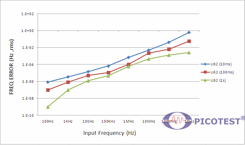
该图不包括触发错误的影响。 为了给这个误差项的附加效应设置一个上限,有必要从正确的图表中确定频率误差并添加一个触发误差项,如下等式:
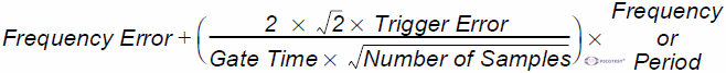
外部源和输入放大器噪声可能会提前或推迟定义测量开始和结束的触发点。 由此产生的时序不确定性是信号压摆率和寄生噪声尖峰幅度(相对于输入迟滞带)的函数。
相对于单个触发点的 (rms) 触发误差为:

B. 预设值和保存/调用信息
※ 注意:U6220A 不提供绿色通道 2 的功能。|
|
Value at *RST |
In Save/Recal |
In non-volatile memory |
|
|
Input impedance |
CH1 |
1E+6Ohms |
yes |
no |
|
CH2 |
1E+6Ohms |
yes |
no |
|
|
Input Attenuation |
CH1 |
×1 |
yes |
no |
|
CH2 |
×1 |
yes |
no |
|
|
Trigger Level |
CH1 (percent) |
50 |
yes |
no |
|
CH2 (percent) |
50 |
yes |
no |
|
|
CH1 (volts) |
0 |
yes |
no |
|
|
CH2 (volts) |
0 |
yes |
no |
|
|
Trigger Slope |
CH1 |
positive |
yes |
no |
|
CH2 |
positive |
yes |
no |
|
|
Sensitivity |
CH1 |
Medium |
yes |
no |
|
CH2 |
Medium |
yes |
no |
|
|
Scale |
1 |
yes |
no |
|
|
Offset |
0 |
yes |
no |
|
|
Limits parameters |
Limit test on/off |
off |
yes |
no |
|
On fail stop/go on |
go on |
yes |
no |
|
|
Lower limit |
0 |
yes |
no |
|
|
Upper Limit |
0 |
yes |
no |
|
|
Stats parameters |
Stats on/off |
off |
yes |
no |
|
Measurement count |
100 |
yes |
no |
|
|
Display measurement/stats |
measurement |
yes |
no |
|
|
Use all/in limits |
all |
yes |
no |
|
|
On-single measurement |
1 |
yes |
no |
|
|
Timebase |
auto |
yes |
no |
|
|
Trigger Offset Cal Parameters |
Channel 1 trigger offset Inp1 cal |
no |
yes |
|
|
Channel 2 trigger offset Inp2 cal |
no |
yes |
||
|
Channel 1 trigger offset Att1 cal |
no |
yes |
||
|
Channel 2 trigger offset Att2 cal |
no |
yes |
||
|
Trigger Gain Cal Parameters |
Channel 1 trigger gain Inp1 cal |
no |
yes |
|
|
Channel 2 trigger gain Inp2 cal |
no |
yes |
||
|
Channel 1 trigger gain Att1 cal |
no |
yes |
||
|
Channel 2 trigger gain Att2 cal |
no |
yes |
||
|
Time Interval Offset Cal Parameters |
Fine1 |
no |
yes |
|
|
Fine2 |
no |
yes |
||
|
Quick |
no |
yes |
||
|
Timebase cal Parameters |
no |
yes |
||
C. 一般规格
※ 注意:U6220A 不支持项目 1 ~ 4 中的绿色配件。
| Item | Limitation & description |
| Power Supply Voltage | 100V/240V ± 10% 50Hz~60Hz ± 10% |
| 100V/120V ± 10% 400Hz ± 10% | |
| Power Requirements | Max. 80VA (30W Typtical) |
| Operating Humidity | Maximum relative humidity 80% for temperature up to 31 ℃ decreasing linearly to 50% relative humidity at 40℃ |
| Operating Environment | 0 to 55 ℃ |
| Storage Temperature | - 40 ℃ to 70 ℃ |
| Operating Altitude | Up to 2000m |
| Dimensions for Rack (WxHxD) | 214.6 x 88.6 x 346.9 mm |
| Weight | 3130 g / 2887 g |
| Safety | IEC61010-1:2010/EN61010-1:2010 (3rd Edition) |
| IEC61010-2-030:2010(1st Edition)/ | |
| EN61010-2-030:2010 | |
| EMC | EN61326, IEC61000-3, IEC61000-4 |
| Warm-up Time | 1 Hour |
| Warranty | 1 Year |
| Accessory |
1. U6200-opt04: Rear panel input module (CH1/CH2) 2. U6200-opt05: Rear panel input module (CH1/CH2/CH3) 3. M3500-opt04: GPIB Card |
※注1:配件必须在Picotest中组装。
※注意2:不要将设备放置在难以操作断开装置的位置。
※ 注意 3:文件中应指示不要用额定值不足的电源线更换可拆卸的电源线。
U6200-OPT04 : Rear Input (CH1/2)模组
U6200-OPT05 : Rear panel input (CH1/2/3)模组
M3500-OPT04 : GPIB卡